Layout of Exception Handler Stack Frame
In the high end of the WC34020's memory there are 4 pairs of words used to specify how interrupts should be handled. One pairs is associated with each of the 4 classes of exceptions just described. The pair associated with traps is called the trap vector. The pairs associated with interrupts are called interrupt vectors. The first word in each pair is used as the address of the handler routine that should be invoked when the corresponding exception occurs. Before this routine is invoked, the value in the second word of the trap or interrupt vector is loaded into the processor status register.
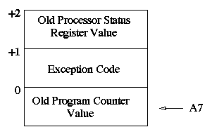
When a trap or interrupt handler is invoked, the processor essentially executes a CALL passing two parameters to the handler. A 3 word frame is allocated on the stack. The layout of an exception hander frame is shown in the figure below.

Layout of Exception Handler Stack Frame
The stack pointer register (A7) is adjusted to point to the last word of the frame (the trap or interrupt handler will typically execute a LINK instruction once it gets control to save and update the frame pointer register (A6) and decrement the stack pointer to make room for any local variables). The previous value of the PC register is stored in the last word of the frame as in a normal call. In addition, the value of the processor status register from before the exception is stored in the location normally reserved for the first parameter to a procedure. Finally, a code indicating the cause of the exception is stored in the word that would usually hold a procedure's second parameter.
The meaning of the code passed to an exception handler depends on the type of exception involved. For all interrupts, the code passed is the address in memory of the device register associated with the completion that causeed the interrupt. For an input completion on a terminal, this will be the address of the terminal's input buffer register. For an output completion, the address of the associated output buffer register will be passed. For timer interrupts, the address of the timer status register is used. Finally, for traps, the following codes are used.